Showing posts with label Power distribution. Show all posts

Monday, 12 November 2018

POWER FACTOR

Power factor:

In power system, three quantities are most important;
                1) Voltage
                2) Current
                3) Frequency
Power quality is an important concern in the power system because it affects the voltage, current, and frequency. The power factor is an important aspect for improving power quality of supply. A load with low power factor has good efficiency and it can save a considerable amount of cost. For, this reason, majority of the utility companies demand in the reduction of reactive power. If reactive power demand decrease, the power factor will improve.
 There are three types of power;
                1) Apparent power
                2) Active power
                3) Reactive power

 1) Apparent power: 

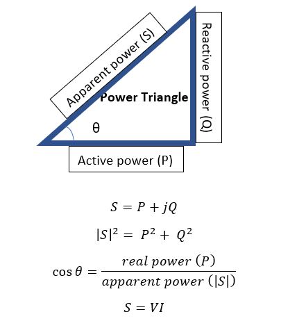
                               The apparent power is denoted as ‘S’. It is the product of the RMS voltage and current. Volt-amperes or VA is unit of the apparent power.
                                S = V x I                 for single phase apparent power
                                S = 1.73 V x I       for three phase apparent power
                                                                                Where V is phase voltage and I is line current

2) Active Power:

                               The active power is also known as true power or real power. This power is a useful power for the load. The unit of the active power is WATT (W) and it is denoted as P. WATT is a very small unit, so power is measured in kW or MW. The active power is carried out in the power system by the part of the current. This current is always in phase with the supply voltage. The real work cannot be done when the current is out of phase with the supply voltage.
3) Reactive power:  
                              The reactive power is a part of an apparent power which is out phase with the real power. This is happening in the power system by reactive elements like inductors and capacitors. This power does not use for the load. The reactive power is also known as the imaginary power. The unit of the reactive power is volt-ampere-reactive (VAR).

Power factor: 

                               The power factor is the ratio of active power (true power) to the power supplied by the power system (apparent power).
                                POWER FACTOR = REAL POWER / APPARENT POWER
                                                                          PF = P/S
In power triangle, θ is the angle between current and voltage. Power factor is also defined as the cosine angle between the phase voltage and the line current.
                                                                             PF = cos θ
Power factor is a dimensionless quantity. The range of power factor is between -1 to 1. In an ideal power system, the power factor is unity (1), means that there is only real power is available. There is absent of reactive power. But in the actual power system, we can not ignore the reactive power and it always is present in the power system. So, in the actual power system, the power system can not unity, but for good quality of supply, we try to maintain power factor near to the unity.
In the power system, we use FACTS devices to improve the power factor. 

Thursday, 22 March 2018

Energy meter


What is Energy meter???

The energy meter is nothing but a device or instrument which is used to measure the amount of electrical energy consumed by the consumer or the load. This load can be domestic, commercial or industrial. SI unit of electrical power is watt. So, this meter is also known as watt-hour (Wh) meter. If an electric load is consumed one kilo-watt power in one hour, it is considered as one kWh consumption or one unit of energy is consumed. These meters are installed at every place where utility is supplying electrical energy. 
The energy meter is always connected in series with the load. The load will be single phase or three phase and according to the type of load, energy meter is classified as a single-phase meter or three phase meter. For single phase or lower load, energy meter can directly connect with load but in case of higher load (industrial-3-Φ), step down current transformer is used to reduce current.
Basically, these meters are measuring an instantaneous voltage and current, and calculate instantaneous power by multiplying the voltage and current. To find final energy utilization, instantaneous power is integrated over a period of time.
According to working principle, energy meter is classified into three types;
               1)      Electro-magnetic induction type energy meter
               2)     Electronic energy meter
               3)     Smart energy meter

Electro-magnetic induction type energy meter

Construction: This energy meter works on the principle of electromagnetic induction. These meters are not used in present system. This energy meter consists of two electromagnets and one aluminum disc. These two electromagnets are made up of laminated silicon steel. Both electromagnets are carried two windings. The upper electromagnet has M-shaped core and consists of a coil, which is known as pressure coil or voltage coil. The upper electromagnet is known as shunt magnet. The lower electromagnet is known as a series magnet (U-shaped) and carries two coils, which is known as current coils. The pressure coil is directly connected to the supply. So, current passes through this coil is proportional to the shunt voltage. The pressure coil consisting of many turns of thin wire and the current coil consisting of few turns of thick wire. In the lower part of shunt magnet, the copper band is placed, which provides frictional compensation and the shunt magnet flux.
The Al disc is mounted on a spindle between two electromagnets. This disc can easily rotate on the vertical shaft without any friction. The permeant magnet is placed near the Al disc. This magnet is known as break magnet.
The registering system is used to record the number of rotations of Al disc. Their rotation is directly proportional to the electrical energy consumed by the load.

Working: The Al disc is placed between the two electromagnets. The voltage coil is connected to supply voltage. The magnetic field induced in the voltage coil is proportional to system voltage and the magnetic field induced in current coil is proportional to current flow to the load. These both fields are perpendicular to each other and because of the magnetic fields, the eddy current is produced in the Al disc. The torque is produced due to the interaction of the eddy current and magnetic field, which creates a force on the disc and disc starts rotating. This torque is directly proportional to the product of the voltage and current.


Advantages:
          1)      Cost of this meter is less compared to electronic energy meter.
          2)     Simple in construction and maintenance is easy.
          3)     High torque to weight ratio.

Disadvantages:
          1)      Less accurate
          2)     Easy to tamper and less secure

Electronic energy meter:

Electronics energy meter is classified into two parts;
               1)      Analog energy meter
               2)     Digital energy meter.
In analog energy meter, the magnitude of voltage and current is obtained from the potential transformer and current transformer respectively. These analog values are converted into digital samples with the help of analog to digital converter (ADC). These samples are converted into frequency signals by a frequency converter. It is used to drive counter system, which integrates this samples over time and results in the reading of power consumption. Analog energy meter is more accurate compared to electromechanical energy meter but less accurate compared to digital energy meter.

In digital energy meter, microprocessor or digital signal processor is used. Similar to an analog energy meter, voltage and current transducers are connected to an analog to digital converter and it is connected with the microprocessor. The voltage and current samples are multiplied in the microprocessor. The phase angle between voltage and current is measured by a microprocessor which is used to calculate reactive power and power factor. To perform this tasks in a microprocessor, it is programmed and it is able to calculate parameters like; electrical power consumption, power factor, reactive power, voltage, current, date & time and charges according to the tariff. Digital energy meter has an LCD or LED display, which is used to display parameters.
The digital energy meter is more accurate compared to analog and electromechanical energy meter and lesser chances of tampering and energy theft in a digital energy meter. But the installation cost of digital energy meter is high compared to analog and electromechanical energy meter. The performance of digital energy meter is depending on the microprocessor.


Smart energy meter:

The smart energy meter is the next generation of an electric meter. The smart meters are installed in developed countries.
Advantages of the smart energy meter,
             1)      It can detect outage
             2)     It can limit the demand
             3)     Record consumer consumption
             4)     Remote disconnection and reconnection
             5)     It can monitor quality of supply
             6)     Advanced Communication system
The smart has the ability to measure the power in both directions; utility to load and load to the utility. For example, the smart meter is installed at a home and a solar rooftop is also installed. Let us assume that, in present condition, generation of solar is higher than a load, in this condition power will transfer from load (home) to utility and if generation is less than the demand, in this condition, power will transfer from utility to load. In this case, the meter can measure the power in both directions.
The smart meter has an advanced communication system for data transfer. It can transfer data to the utility like energy consumption, voltage, and current value, power factor etc. The power theft is not possible in case of a smart meter. The consumer can directly pay money through the meter and not need to visit the consumer for meter reading. It can connect to your smartphone also so, you can get details of all parameter from your phone.
The smart meter has only one disadvantage that is cost. The cost of this meter is very high and to develop and install the smart meter advance technology is required.

Tuesday, 6 March 2018

Monday, 5 March 2018

GIS- Gas Insulated substation


GIS- Gas Insulated substation

Because of their high reliability, easy maintenance, and small ground space requirement, the gas insulated substations (GIS) have been used in power systems over the last three decades.
The GIS is totally enclosed and therefore is free from any atmospheric contamination. Conductive particles, particle discharges, and contamination are factors which affect the life of GIS.

To reduce the breakdown level of Gas insulated systems, conductive particles inside the enclosure are known. From conductive particles, partial discharges can develop, contamination, and defects during the manufacturing process, etc.

Because of its compactness, the GIS requires less number of lightning arresters compared to a conventional substation.

Air can withstand very high voltages for very short time. However, the withstand voltage falls off considerably, as the duration of voltage increases.

SF6 exhibits a flat characteristic. For GIS, the ratio of basic lightning impulse level is close to unity, whereas this ratio varies between 0.6 and 0.86 for the conventional substations.

GIS are in service up to the highest voltage level of 800 kV. GIS is meeting almost all the requirements in urban, industrial and rural areas.

The SF6 gas insulated substations were almost exclusively used in the initial stages. This type of substations is more popular where space limitations, site restrictions or exponential ambient conditions. In this condition, it is difficult to use conventional air-insulated substations.


Characteristics of SF6:

1. SF6 is colorlessly, odorless and a chemical neutral gas Characteristics of SF6 chemical neutral gas.

2. SF6 is 5 times heavier than air and it is not toxic and has no dangerous components inside.

3. SF6 is no hazardous material.

4. SF6 has no eco-toxic potential.

5. SF6 has no impact for the ozonosphere.

6. SF6 is a potent greenhouse gas.

7. SF6 has excellent electrical characteristics.


Features of GIS:

1. For standardized component models, widespread application of aluminum enclosure materials

2. The enclosures have low eddy-current losses, good conductivity, and a high resistance to corrosion and the enclosures is light in weight.

3. Easy handling, reduced stresses on foundation and support structure are additional features for the construction of GIS.

4. Good co-ordination between the manufacturer and the user, standard arrangements can be easily modified and extended.

5. For the separation of gas compartments, a gas-tight barrier insulator in switchgear serve and during maintenance prevents neighboring switchgear parts from being affected.


Components of GIS:

1. Circuit breaker

2. Disconnector switch

3. Earthing switch

4. Current transformer

5. Voltage transformer

6. Bus bar & connectors

7. Power transformer

8. Surge Arrester

9. Cable termination

10. SF6 / air or SF6 / oil bushing


Advantages of GIS:

During the last fifteen years, the application of GIS has been very rapid. The growth in GIS application is because of the following special advantages of GIS;

1. They offer to save on land area and construction costs.

2. Because of lesser maintenance, downtime and repair costs, more optimal life cycle costs.

3. Due to the earthed metal housing of all high voltage parts, greatly improved safety and reliability. SF6 gas as insulation much higher intrinsic strength.

4. Based on large factory assembled and tested shipping units, short on-site erection times.

5. Due to non-exposure of the use of high voltage parts to atmosphere influences high service reliability.

6. Reduction in radio interference with the use of earthed metal enclosures

7. Use as mobile substations for transportation to load centers on standard tracks. These substations can be located closer to load centers thereby reducing transmission losses and expenditure in the distribution network.

8. Insensitivity to external influences because of grounded metal enclosures.

9. It is not necessary that high voltage or extra high voltage switchgear has to be installed outdoors.


Disadvantages of GIS:

A lot of problems encountered in practice need fuller understanding, although GIS has been in operation for several years. Some of the problems are:

1. Switching operation generate Very Fast Transients Over Voltages.

2. Very Fast Transients Over Voltages may cause secondary breakdown inside a GIS and Transient Enclosure Voltages outside the GIS.

3. Field non-uniformity reduce withstanding levels of a GIS.

4. Prolonged arcing may produce corrosive/toxic by-products.

5. Support spacers can be weak points when arc by-products and metallic particles are present.