Showing posts with label Electrical Machines. Show all posts

Thursday, 27 December 2018

OPEN CIRCUIT TEST ON TRANSFORMER

In the previous article, we have seen that there are four tests of the transformer.

2) Open circuit test
3) Short circuit test
4) Sumpner’s test or back to back test

In this article, we will explain the open circuit test of the transformer.

Open circuit test should be conducted at rated flux in the transformer core. The rated flux can be achieved by keeping other winding terminals open and keeping the existing transformer at rated voltage and frequency.


The objectives of open circuit test are:
a) To find the constant losses of the transformer.
b) To find shunt branch parameters of equivalent circuit R0 and X0.
c) To separate iron losses and find hysteresis loss and eddy current loss.

This test is conducted on the LV side of the transformer because at LV side low range volt meter and watt meter are sufficient to conduct the test. Another reason is that the magnitude of the no-load current is more on the LV side. So, we can measure no-load current more accurately compared to the HV side. Therefore, in most of the cases, this test is conducted on the LV side of the transformer.


Generally, for this test LPF wattmeter is used because the power factor is at nearly 0.2 lag. The measurements are primary voltage (V1), no-load current (I0) and no-load power (W0). This entire test can be divided into three parts.

1) Find out R0 and X0:


Above circuit represent approximate equivalent circuit of the transformer. From this circuit,

R0 = V1/Iw
X0 = V1/Iu
Where, Iw = core loss current = I0 cos фo
and Iu = magnetizing current = Iu sin фo
W0 = No load power = V1I0cosфo
Cos фo = W0/V1I0

From the measurement, we have no-load current (I0), no-load power (W0) and voltage (V1). First, we have to find Iw and Iu. From the above equation, we can find out R0 and X0.


2) To find out constant losses:
W0 = losses in transformer under no load condition

W0 = Iron loss + dielectric loss + No load primary copper loss

The iron loss and dielectric loss is considered as a constant loss. The dielectric loss is negligible in this case.
Iron loss = W0 – I02R1

Now, by test measurement, we have a value of W0 and I0. But we don’t have the value of R1. Therefore, the Kelvin double bridge method is used to measure the value of resistance R1. In this condition, we neglect the primary copper loss and dielectric loss. so, watt meter reading during open circuit test is approximately considered as an iron loss.


3) Separation of iron losses: The iron loss can be divided into two parts; the hysteresis loss and eddy current loss. This test should be conducted with variable frequency and voltage, in such a way that the ratio of voltage and frequency (V1/f) remains constant.

The first thing to do here is to apply rated voltage and rated frequency and note down the reading of watt meter and frequency meter. After that, apply to reduce voltage and set frequency in such a way that V1/f ratio remains same and note down the reading of wattmeter and frequency meter.


By repeating this procedure with changes in voltage and frequency, we can draw a graph for (Wi/f) vs frequency. The find constant A and B, where A is the y-intercept and B is the slope of the curve.

Now from this you can calculate the hysteresis loss and eddy current loss at rated frequency and voltage by below equations.

Hysteresis loss at rated frequency = A x rated frequency

Eddy current loss at rated frequency = B x square of the rated frequency.

Wi = Af + Bf2
Wi/f = A + Bf
m = slop of straight line = tan θ = B

Saturday, 15 December 2018

POLARITY TEST IN TRANSFORMER


If the transformers are used in the parallel operation or used in the polyphase circuit, the polarities of primary and secondary terminals must be known at any instant. Due to the potential difference between two points, the current can from the high voltage point to low voltage point. The polarity is nothing but it describes the direction of the current flow. The dot convention is used to identify the polarity of two windings.


- If a current enters to the dotted terminal of one winding, the polarity of the voltage on the secondary winding will be positive at the dotted terminal.

- If current leaves to the dotted terminal of one winding, the polarity of the voltage on the secondary winding will be negative at the dotted terminal.


Assume the primary side of the transformer at a particular instant of time the polarity is A1 which is positive with respect to A2. In this case, if the voltmeter reading V = E1 + E2 means additive polarity, then B1 is negative and B2 is positive at any instant of time A1 is positive and A2 is negative.
Replace dot marks at either positive polarity terminals or negative polarity terminals on both sides.


During this polarity test, if the voltmeter reads sum of two EMFs, the secondary side terminals should assign as opposite polarity with respect to assumed primary polarity.


If voltmeter reading is V = E1 – E2 means negative polarity (difference of two EMFs), then the secondary side terminal should be assigned with the same polarity as assumed primary side.


This test can be easily implemented on a low voltage range of the transformer and cannot be used for a high voltage range of transformer.

DC kick test:

This method is used for low voltage range transformer as well as a high voltage transformer. In this method, the transformer is excited with DC supply. This excitation is not continuously. It is momentarily excitation.


If you give continuous excitation of DC supply than it is possible to damage the transformer because very high current will flow in the primary. So, never excite transformer with DC supply. If you want to excite transformer with DC, excite HV winding because it has a high resistance compared to LV winding.

When DC voltage is applied to the primary winding terminal A1 which is positive with respect to A2. If the switch is closed and opened and momentary supply is given to primary winding of the transformer. In this case, the galvanometer observed a kick.


If the kick is in the forward direction, secondary side terminals should be assigned as the same polarity of primary winding terminals. If dot notation is to be applied, a pair of similar terminals should be assigned with dot marks.

If the kick is in the backward direction, secondary side terminals should be assigned as the opposite polarity of primary winding terminals. If dot notation is to be applied, a pair of dissimilar terminals should be assigned with dot marks.

Friday, 14 December 2018

DIFFERENCE BETWEEN POWER TRANSFORMER AND DISTRIBUTION TRANSFORMER


In the previous article, we have discussed the total losses occurred in the transformer. For good experience, read this article in DESKTOP MODE in any browser.


In this blog, we will discuss the difference between the power transformer and distribution transformer with design and operational perspective. 


Power Transformer

Distribution transformer
1
The power transformer is used in the transmission network
1
The distribution transformer is used in the distribution network
2
Voltage level > 33 kV
2
Voltage level < 33kV
3
Fewer Load fluctuations
3
More Load fluctuations
4
The consumer is not directly connected
4
Consumers are directly connected
5
While designing copper losses are kept the minimum.
5
While designing iron losses are kept the minimum.
6
CRGO steel is used in the core of this transformer.
6
Amorphous steel is used in the core of this transformer.
7
Copper losses and iron losses take place steadily throughout 24 hours.
7
The copper loss takes place based on the load cycle of the consumer and iron loss take place steadily throughout 24 hours.
8
Full load copper loss is almost the same as an iron loss.
8
Full load copper loss is twice of the iron loss
9
Efficiency maximum occurs at nearer to the full load
9
Maximum efficiency occurs at 70-75% of full load.
10
Specific weight is less
10
Specific weight is more
11
Average load on the power transformer is almost nearer to the full load.
11
Average load on the distribution transformer is 70-75% of the full load.

 Watch video of Transformer explosion.


Thursday, 13 December 2018

TRANSFORMER LOSSES


There are four types of losses occurs in the transformer and that is,     
      1) Copper loss
      2) Iron loss
      3) Stray loss
      4) Dielectric loss
Out of above mentioned losses, copper loss and iron loss can be considered as major losses and stray loss and dielectric loss can be considered as minor losses. Let’s explain this in details.


1) Copper loss: There are two winding in the transformer; primary winding and a secondary winding. The copper loss is nothing but, the losses occur due to the winding resistance. The copper loss is also known as I2R loss or cu loss. If primary winding resistance is R1 and secondary winding resistance is R2, then

Total copper loss in transformer
(I1^2) R1 + (I2^2) R2

Where I1 is full load primary current
I2 is full load secondary current

From the above equation, we can see that copper loss is directly proportional to the square of the load current. It means that, as the load current changes, the copper loss also changes. So, this loss is considered as a variable loss.


2) Iron loss: This loss takes place in the core of the transformer due to the time-varying nature of flux in the core. So, the iron loss is also known as core loss. The total iron loss is divided into two parts; hysteresis loss and eddy current loss.

          (A) Hysteresis loss:  Whenever it is subjected to alternating nature of magnetising force, the hysteresis loss occurs due to the reversal of magnetisation of the transformer core. In this case, after every half cycle, the domain present in the magnetic material will change their orientation. The power consumed by this change of orientation after every half cycle is known as hysteresis loss.
The magnetic reversal of the transformer core is plotted with the help of the BH curve and it represents as below figure.


The hysteresis loss occurs in one cycle is equal to the area enclosed with the one hysteresis loop.
The hysteresis loss can be determined with the Steinmetz's formula. Which is given as
Where n= Steinmetz coefficient = range 1.5 to 2.5
F = supply frequency
V = volume of core
X = Steinmetz exponent = 1.6 for silicon steel

          (B) Eddy current loss: The eddy current loss is nothing but, the I2R loss present in the core of the transformer due to the production of the eddy current in the core. The eddy current is produced because of the conductivity of the core.

The eddy current loss is directly proportional to the conductivity (σ) of the core.
Rse = the resistance offered by the core to flow of eddy current.
Rse is inversely proportional to the conductivity.

By reducing the conductivity, the eddy current can be reduced. It is possible to reduce conductivity without affecting magnetic properties by adding silica content and by using laminated core.


3) Stray loss: It can be divided into two parts; copper stray loss and iron stray loss.

          (A) Copper stray loss: This loss occurs only under full load condition due to the leakage flux. This loss is the additional I2R loss due to stray current within the conductor. This loss is considered as a variable loss. Instead of the solid conductor, the stranded conductors are used to reduce the copper stray loss and by this way, the skin effect of winding is also reduced.

          (B) Iron stray loss: The iron stray loss is the additional iron loss occurred due to the auxiliary iron parts like transformer tank, steel channels, and conservation tank. In this auxiliary iron parts, due to the leakage flux, this loss is produced. This loss is less in shell type transformer compared to the core type transformer.

The leakage flux is directly proportional to the load current. So, this loss is also considered as a variable loss. The iron stray loss is just 0.5% of full load output.


4) Dielectric loss: This loss is produced in the insulating material of the transformer. In insulating material, the free electrons are not available. When a voltage is applied, a small amount of current will flow through this due to the conversion of atoms. There is displacement of charges and the current produce due to this is known as displacement current.

The process of conversion of atoms into electric dipole is known as polarization. The dielectric loss is depending on applied voltage and it is independent of load current. So, this loss is considered a constant loss. This loss is 0.25% of full load output.

Wednesday, 27 June 2018

testing of DC machine


The testing of dc machine:
The testing of dc machine is required for legitimate creation and smooth inconvenience free task. The tests which are fundamentally required for these reasons for existing are –
1) Open circuit test
2) Short circuit test
3) Load test
4) Efficiency test

Open Circuit Test:
The open circuit test is expected to decide the open circuit characteristic or magnetic characteristic for a dc machine. The open circuit test gives the mmf and henceforth the excitation current or field current expected to produce the required voltage on no heap at a settled speed. The open circuit characteristic curve demonstrates the variety of instigated emf as an element of field current at consistent speed and zero load current.
This curve is for all intents and purposes controlled by running the machine as a separately excited generator on-stack. This curve is additionally called no load saturation curve as it gives the saturation characteristic for the generator.
Short circuit Test
The short circuit test is expected to decide the voltage drop over the armature at any load current. In this testing of DC machine, the armature is short-circuited with an ammeter to get the short circuit current. Short circuit test gives the short circuit characteristic curve which demonstrates the variety of short circuit present as a component of excitation current.
Load Test
The load testing of DC machine is expected to decide the rating of a machine. When we run a machine, at that point some energy is lost in the machine, which changes over into the heat and cause temperature rise. In the event that a machine creates excessively heat then it can influence the protection of the machine and at last it can cause the breakdown of the machine. In this manner, the load must be set to an esteem that it can work inside as far as possible. The most extreme estimation of the load that can be conveyed by the machine with no mischief is known as the consistent rating of that machine.
Determination of Efficiency
The Efficiency of DC machine like some other machine is dictated by the ratio of output power to that of the input power.

There are three techniques for deciding the Efficiency of a machine.
1) direct technique
2) indirect technique
3) Regenerative technique
The first condition is giving a thought regarding the immediate estimation of the productivity. In this strategy the machine is completely stacked and the yield is straightforwardly estimated. This strategy for estimation is connected for the little machines.
The second and third conditions are giving a thought regarding the aberrant estimation of the effectiveness.
Aberrant strategy is useful of deciding the proficiency of shunt wound generator and compound injury generators. In this strategy it is required to decide to decide the misfortunes as it were. Along these lines, control supply is required to supply the misfortunes just without stacking the machine. For the regenerative technique for deciding effectiveness, it is required to have two indistinguishable machines. One machine is utilized as engine and drives the other and the other is utilized as generator and input the power into the supply. Two machines are mechanically coupled. Consequently, the misfortunes can be resolved on the grounds that the inside influence attracted is just to supply misfortunes of the two machines. But these testicles, the protection test and the test for making the recompense palatable is done while developing the machine.

Tuesday, 10 April 2018

DC motor

DC machine:

DC machine includes the function of generator and motor. Same machine you can use as a generator or motor. There is no change in construction.

If you supply electrical energy to DC machine, it will give you mechanical energy or rotational energy. This is known as motor function. The principle of motor is " whenever a current caring conductor is placed in a magnetic field, it will experience a force and two equal and opposite direction force will create a torque."

If you have mechanical energy in terms of rotation (by prime mover), you can generate electrical energy with the help of DC machine and this function is known as generator. Generator works as principle of electromagnetic induction.


Different parts of DC machine:

1) Yoke:
  • It is used to protect internal parts of DC machine.
  • Provide support to the pole.
  • Complete magnetic path.
          Yoke is made up Cast iron

2) Pole:
  • Pole is used to produce magnetic flux inside the DC machine. Pole is made up of low reluctance material like cast iron or cast steel. 
3) Pole shoe:
  • Pole shoe is used to spread the magnetic field produced by the poles. Pole and pole shoe are laminated in large machine.
4) Armature:
  • Armature provide housing to the armature winding
  • It completes magnetic flux path
          Armature is made up of Cast iron. Armature is laminated to reduce the eddy current losses.

5) Armature winding:
  • whatever current is produced in case of generator, that current is produce in armature winding and in case of motor, voltage is supplied to the armature winding. It made up of copper.
6) Field winding:
  • Field winding is placed on the pole to produce magnetic field inside the DC machine. It is made up from copper.
7) Commutator:
  • In case of generator, commutator is used to convert AC current into DC current. In other words, it functions as a rectifier.
  • In case of motor, commutator is used to produce unidirectional torque. 
8) Brush:
  • Brushes are used to carry current from and to commutator. It is made of carbon.
9) Shaft:
  • Shaft is used to transfer mechanical power from prime mover or to load.
Classification of DC motor:
Motor is used to convert mechanical energy into electrical energy. As shown in construction of DC motor, there are two winding is used. One is field winding and second is armature winding. According to connection of this winding, DC motor is classify into main two parts; 
  1. Separately excited 
  2. Self excited
Self excited is further classify into three types;
  1. Series motor
  2. Shunt motor
  3. Compound motor
1) Separately excited: In separately excited motor, field winding and armature winding is not physically connected but this winding is magnetically connected. Here, the field coil is energized from a separate DC voltage source and the armature coil is also energized from another source. Armature voltage source may be variable but, independent constant DC voltage is used for energizing the field coil. So, those coils are electrically isolated from each other, and this connection is the specialty of this type of DC motor.

Application: Separately excited dc motors have industrial applications. This type of motors is used in trains and for automatic traction purposes. They are often used as actuators. 


2) Self Excited DC motor: In self excited DC motor, field winding and armature winding is physically connected. The current in the winding is supplied by the machine or motor itself. Self-excited DC Motor is further divided into three parts according to connection of both winding and this is known as shunt wound, and series wound motor. They are explained below in detail.

  • Series DC motor: In  this case, the armature winding and field winding are connected in series so, the entire armature current flows through the field winding. The series wound self excited dc motor is diagrammatically represented as below figure for better understanding. In a series dc motor, the speed varies with load and operation wise this is its main difference from a shunt wound dc motor.


Application of DC series motor:
  1. This type of motor has good speed regulation even as the load varies.
  2. It has high starting torque so it has wide application in conveyors,trains,compressors etc.
  3. It is typically used were adjustable speed is required.
  • Shunt DC motor: In case of shunt wound DC motor, the armature winding and field winding are connected in parallel. So, the field winding are exposed to the entire terminal voltage. The shunt wound dc motor is a constant speed motor, as the speed does not vary here with the variation of mechanical load on the output. 

Application of DC shunt motor:
  1. A DC shunt motor is constant speed motor(as for a given field current the drop in speed from no load to full load is less than 6 to 7 % ) so it is used where constant speed is required.But SCIM is replacing it in industry.
  2. When the driven load needs a wide range of speed variation both below and above base speed, this motor is used.(e.g:lathe)
  3. DC shunt motor is easy to control using VFD(variable frequency drive) so it is used in the places where variable speed is required
  • Compound motor: The compound excitation characteristic in a dc motor is obtained by combining the operational characteristic of both the shunt and series excited dc motor. The compound wound self excited dc motor or simply compound wound dc motor essentially contains the field winding connected both in series and in parallel to the armature winding. The excitation of compound wound dc motor can be of two types depending on the nature of compounding.
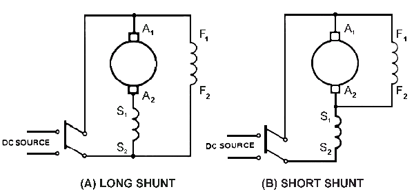
  1. Cumulative Compound DC Motor (Long Shunt): In which the shunt field flux assists the main field flux, produced by the main field connected in series to the armature winding. 
  2. Differential compound dc motor (Short shunt): In which the arrangement of shunt and series winding is such that the field flux produced by the shunt field winding diminishes the effect of flux by the main series field winding.The net flux produced in this case is lesser than the original flux and hence does not find much of a practical application.
Application of compound DC motor:
Cumulative compound wound motors are virtually suitable for almost all applications like business machines, machine tools, agitators and mixers etc. Compound motors are used to drive loads such as shears, presses and reciprocating machines.

Speed control of DC motor:

     Three types of DC motor; series motor, shunt motor and compound motor. In these motors, speed can be change by changing below parameter,
                1)      Terminal voltage of the armature V
                2)      External resistance in armature circuit Ra
                3)      Flux per pole φ
Let’s start with speed Control of DC Series Motor:
             Speed control of DC series motor can be done either by armature control or by field control. Armature Control of DC Series Motor. Connection diagram (circuit diagram) of DC series motor is as below figure. Speed adjustment of DC series motor by armature control may be done by any one of the methods that follow.

              A) Armature Resistance Control Method for DC Series Motor:

x


IArmature resistance control method, a variable resistance is directly connected in series with the supply. This reduces the voltage available across the armature and hence the speed falls. By changing the value of variable resistance, any speed below the normal speed can be obtained. This is the most common method employed to control the speed of DC series motors.
              B)      Flux control method DC Series Motor:
In Flux control method, the flux produced by the series motor is varied. The variation of flux can be achieved in the following ways:
               1)     Field diverters - In this method, a variable resistance (called field diverter) is connected in parallel with series field winding.  A part of the line current passes through this diverter and thus weakens the field. Since N ∝ 1/ϕ, speed also varies with field flux. The lowest speed obtained by this method is the normal speed of motor when the current through diverter is zero, i.e., diverter open circuited. 
           2)     Armature diverter - In order to obtain speeds below the normal speed, a variable resistance (called armature diverter) is connected in parallel with the armature. The diverter reduces the armature current. As a result, flux get increased. So, the speed decreases since N ∝ 1/ϕ.
          3)   Tapped field control - In this method, the flux is reduced (and hence speed is increased) by decreasing the number of turns of the series field winding. The switch can short circuit any part of the field winding, thus decreasing the flux and raising the speed. With full turns of the field winding, the motor runs at normal speed and as the field turns are cut out, speeds higher than normal speed are achieved.


The speed control of a DC Shunt motor can be achieved by the following methods:
           1)      Flux Control Method
           2)      Armature control Method
           3)      Voltage Control Method
Flux Control Method DC Shunt motor:
                This method is very frequently used because it is very simple and economic. In this method the speed control can be achieved by varying the flux Φ, because the motor speed N ∝ (1/ Φ) and therefore it is named flux control method. Along with the shunt field winding an adjustable resistance is connected in series as shown in the figure. This adjustable resistance is also known as shunt field rheostat. This shunt field rheostat moderates the shunt current and the flux. As a result, we can only increase the speed beyond the rated speed of the motor. Normally, it allows the speed to increase in the ratio of 3:1 varied speed choices have a tendency to create instability and meager commutation.

Armature Control Method DC Shunt motor
In this method the speed control can be achieved by varying voltage across the armature and the back EMF Eb. This is obtained by connecting an adjustable resistance in series by way of the armature shown in fig. This adjustable resistance is also known as controller resistance Ra. In this method is decreased due to voltage drop in the Ra. Since speed is directly proportional to back EMF. By using this method, the speed can only control lower than the normal speed because the maximum speed is that corresponding to Ra=0 i.e. normal speed.
Voltage Control Method DC Shunt motor
In this process the supply voltage is providing the field current is not the same from that which deliveries the armature. By using this technique, we can avoid the drawback of meager speed regulation and efficiency as we have seen the armature control method. But this method is fairly expensive. So, this method is engaged for bigger size of motor and where the importance is given for efficiency.
Speed control of DC Shunt Motor using voltage control method can be achieved in two ways. They are (A) Multiple Voltage control and (B) Ward-Leonard System.
                      A)      Multiple Voltage Control Method
                                In this method a fixed voltage source is permanently connected across the shunt field of the motor. The armature can be connected across quite a lot of diverse voltages over a right switch gear. The speed of the motor can be controlled by applying the various voltages across the armature. Since the speed is directly proportional to the applied voltage across the armature will be nearly proportionate to the applied voltage across armature. By using shunt field regulator intermediate speed can be obtained in this method.
                      B)      Ward-Leonard System
                                In this system, the field circuit is delivered from an isolated source. From a variable voltage generator, the adjustable voltage for the armature is obtained. The fig above shows the typical Ward-Leonard system. In this system the armature of the DC Shunt motor is directly connected to a generator driven by a constant speed AC motor. The field of the generator is supplied from the exciter (E). The field of shunt motor is supplied from a constant voltage exciter. The Generator voltage can be varied by means of generator field regulator. The voltage applied to the motor may be reversed by backing the field current of generator through controller FC. On occasion, a field regulator is contained within the field circuit of DC shunt motor for additional speed adjustment. By means of this method, the motor can be worked at any speed up to its maximum speed.

Cumulative Compound Motors
Below figure shows a diagram of the cumulative compound motor. It is so called because the shunt field is connected so that its coils are aiding the magnetic fields of the series field and armature. The shunt winding can be wired as a long shunt or as a short shunt. Figure-a and Fig.b show the motor connected as a short shunt where the shunt field is connected in parallel with only the armature. Figure-c shows the motor connected as a long shunt where the shunt field is connected in parallel with both the series field, interpoles, and the armature.
Below figure-B also shows the short shunt motor as a cumulative compound motor, which means the polarity of the shunt field matches the polarity of the armature. You can see in this figure that the top of the shunt field is positive polarity and that it is connected to the positive terminal of the armature. In Fig. b you can see that the shunt field has been reversed so that the negative terminal of the shunt field is now connected to the positive terminal of the armature. This type of motor is called a differential compound because the polarities of the shunt field and the armature are opposite.
The cumulative compound motor is one of the most common DC motors because it provides high starting torque and good speed regulation at high speeds. Since the shunt field is wired with similar polarity in parallel with the magnetic field aiding the series field and armature field, it is called cumulative. When the motor is connected this way, it can start even with a large load and then operate smoothly when the load varies slightly.

FIGURE (a) Diagram of a cumulative compound motor, (b) Diagram of a differential compound motor
You should recall that the shunt motor can provide smooth operation at full speed, but it cannot start with a large load attached, and the series motor can start with a heavy load, but its speed cannot be controlled. The cumulative compound motor takes the best characteristics of both the series motor and shunt motor, which makes it acceptable for most applications.
Differential Compound Motors
Differential compound motors use the same motor and windings as the cumulative compound motor, but they are connected in a slightly different manner to provide slightly different operating speed and torque characteristics. Figure 12-17b shows the diagram for a differential compound motor with the shunt field connected so its polarity is reversed to the polarity of the armature. Since the shunt field is still connected in parallel with only the armature, it is considered a short shunt.
               In this diagram you should notice that Fl and F2 are connected in reverse polarity to the armature. In the differential compound motor the shunt field is connected so that its magnetic field opposes the magnetic fields in the armature and series field. When the shunt field's polarity is reversed like this, its field will oppose the other fields and the characteristics of the shunt motor are not as pronounced in this motor. This means that the motor will tend to over speed when the load is reduced just like a series motor. Its speed will also drop more than the cumulative compound motor when the load increases at full rpm. These two characteristics make the differential motor less desirable than the cumulative motor for most applications.