Showing posts with label Power system. Show all posts

Monday, 17 December 2018

POWER SYSTEM STABILITY


The study of the electrical power system is incomplete without the study of the power system stability. The definition of power system stability is the ability of the power system to return back to a steady state without losing synchronism.


The power system network is a very large network and millions of equipment are operating together in parallel. This all equipment is working in synchronism. If one of the equipment goes out of synchronism by an abnormal condition. It will affect the other equipment and thereby in the worst condition it is affecting the entire network.

Let us consider a small system having five generators. If one generator is going out of synchronism due to any fault, it will affect the other generators. Due to this, the entire system will face connivances. So, in this condition, the faulty generator immediately switched out from the system. If the faulty generator is not switched out, then it will affect the voltage profile of the system. There will be large fluctuation in the voltage.


The power system stability is categorized into a steady state, transient and dynamic stability. The stability limit is defined as the maximum power that can be transferred in a network between source and load without loss of synchronism.

1) Steady state stability: It is the ability of the power system when operating under given load condition to retain synchronism when subjected to small and slow disturbances. The load fluctuation and turbine governors are examples of slow disturbances. The steady state limit is defined as the maximum power that can be transferred without making the system unstable. When the load is increased gradually under steady state condition.


2) Transient stability: It is the ability of the power system when operating under a given load condition to retain synchronism when subjected to large disturbances. The loss of generation, sudden changes in loads, a short circuit in the transmission line and short circuit in the transformer are the examples of the large disturbances in the power system. The time period of the transient study is very less. The transient stability limit is the maximum power that can be transferred without making the system unstable in the large disturbance condition. The transient stability limit is almost lower than the steady-state limit.


3) Dynamic stability: It is the ability of the power system to remain in synchronism after the initial swing until the system has settled down to the new steady state equilibrium condition. If the oscillation does not acquire more amplitude and die out quickly, then the system is said to be a dynamically stable system. The dynamic stability can be improved by the power system stabilizer. The time period of dynamic system study is 5-10 sec and some time it may be up to 30 sec. With an increase of load from the use of automatic voltage regulators and speed governors, if the increase in field current or adjustments in speed setting occur, the stability limit would be increased significantly. The limit under this condition is called the dynamic stability limit.


Tuesday, 11 December 2018

ISLANDING


In an interconnected power system network, all generators are connected in parallel with transmission lines and sharing load according to the capacity of the power plant. 

A large power system network is prone to disturbances. These disturbances are due to various factors like a fault in the major transmission line, sudden shut down of the large capacity power plant and failure in the interconnecting transformer. 

These are the most severe and rare disturbances. In this abnormal condition, the entire system is divided into several parts. Which may or may not alive depending on the availability of generating station and load demand. 


In an interconnected power system, if one generator is failed to supply the power, the load is transferred to another generator and if this generator is not capable to sustain the load, it will be overloaded and shut down. 

By this way, the load is transferred to another generator and in the worst condition, all generators are disconnected from the grid. This condition is known as BLACKOUT or CASCADE TRIPPING.

In the event of severe faults, the part of the power system which has generating station and able to handle a load of that area, that part of the system is planned to separate from the grid is called as islanding


The islanding is the only way to survive from blackout and save entire grid in a severe fault condition. The main objective of islanding is to restrict the fault or disturbance to the range and try to save power plants from cascade tripping.

The islanded part of the system is separated through under frequency or directional power relay and this part may have more than one generating stations. It is also necessary to maintain a balance between the power generation and demand in this area.

How does it work?


In a power system network, a set of protective relays are connected at the bus. If a severe fault occurred in the system, these relays will sense the disturbance and give the trip command to the breaker of that bus and the plant is isolated from the system by opening the breaker. 


The distributed generators are also disconnected from the grid. The DG may get damaged due to high disturbance and possible to shut down. So, it is necessary to disconnect from the grid to protect the DG in case of islanding. These DG set can use to provide the starting power to the generating station while restarting the grid.

Islanding detection techniques:
1) Under-voltage / over-voltage and Under frequency / over frequency
2) Impedance measurement
3) The rate of change of frequency
4) Voltage phase jump detection
5) Harmonic detection


Advantages:
1) Save power system from blackout
2) Improve reliability of the system
3) Reduce outage area and outage cost

Disadvantages:
1) Islanding is dangerous for the utility crew. The utility workers, who may not realise about live wires.
2) The power quality is the main concern in islanding. Because of unsuitable power quality equipment may get damaged.
3) If DG is working in islanding, there is a chance to damage the DG and maintenance cost of DG is very high.
4) The detection of islanding is a very complicated task. However, there are several schemes and algorithms used to detect islanding.
5) If solar power plants are used as DG, the inverter may get confused in islanding condition.

Saturday, 8 December 2018

LOAD DISPATCH CENTRE


In the Interconnected power system, all the generating stations are connected in parallel with the help of the grid. It is most important and necessary to coordinate these all generators for best economical operation. The load dispatch centre is an organisation which coordinates all power stations. The Load dispatch centre is the most link between different parts of the system. The LDC is used to coordinate, planning, control, and monitoring the power demand and generation. The LDC links generation, transmission, and distribution which coordinate the power requirements of the electricity consumer.


The objective of load dispatch centre:

1) It provides system security
2) Islanding facility
3) Optimum use of resources
4) Load forecasting and demand estimation
5) Maintain power quality of power supply which is transmitted through the regional grid.
6) Regulating the system frequency
7) Help to quickly restore the system after any disturbances
8) Reliable operation of the transmission system
9) Matching the power generation to the power demand


10) Communication and SCADA management
11) Responsible for carrying out the real-time operation of the grid with same as the grid standard and the grid code.
12) Analysis of tripping and disturbances
13) Ensures the stability of the power system
14) Supervision and control over the inter-regional links
15) Safety of equipment
16) Outage planning and monitoring
17) Load shedding implementation
18) Reactive power management and voltage control
19) Monitor bilateral power supply agreement


If we consider the Indian power system network, there is one National Load Dispatch Centre (NLDC) and five Regional Load Dispatch Centre (RLDC).

1) National Load Dispatch Centre (NLDC)
2) Regional Load Dispatch Centre (RLDC)
      - Northern Regional Load Dispatch Centre (NRLDC)
      - Southern Regional Load Dispatch Centre (SRLDC)
      - Western Regional Load Dispatch Centre (WRLDC)
      - Eastern Regional Load Dispatch Centre (ERLDC)
      - North-Eastern Regional Load Dispatch Centre (NWRLDC)
3) State Load Dispatch Centre (SLDC)
4) Area Load Dispatch Centre (ALDC)
5) Remote Terminal Unit (RTU)


There are one NLDC is placed in the capital of India and that is Delhi. The NLDC is main LDC and monitors all five RLDC. These RLDC works under the observation of the NLDC. The NRLDC is placed in Delhi, SRLDC is placed in Bangalore, WRLDC is placed in Mumbai, ERLDC is placed in Kolkata and NWRLDC is placed in Shillong.

The SLDC (state load dispatch centres) are placed in all states of the country. The SLDC works under observation of the RLDC. The ALDC works under observation of the SLDC and RTU work under the observation of the ALDC. This is the hierarchy of the LDC.

Tuesday, 27 November 2018

ADVANTAGES OF INTERCONNECTED SYSTEM


In this article, the advantages of the interconnected system are explained briefly. Before this, you must have to know about the concept of interconnected system and problems associated with interconnected system.

Advantages of interconnected power system

1) Use of older plants
2) Economical operation
3) Increase reliability of power supply
4) Exchange of peak load
5) Increase diversity factor
6) Reduce plant reserve capacity
7) Reduce capital and operating cost:


Advantages:

1) Use of older plants: In power system network, there are some old and insufficient generating stations are available which has capacity to carry short peaks of load but these generating stations are not sufficient to run on continuous basis. If system is interconnected than these plants is also connected in system with transmission line and we can use these plants to meet peak load demand and use this with modern plants. By this way, we can meet peak load demand without give extra burden on modern plants with the help of old and insufficient generating station.

2) Economical operation: All the generating stations are working on same frequency and same voltage level. Because of sharing of load among the power plants are done in such a way that all generating stations can work continuously with high efficiency and high power factor. The less efficient and old generating stations are not used continuously and these plants are used only at peak hours. Therefor, in interconnected system makes the economical operation of the power stations.


3) Increase reliability of power supply: In interconnected power system, all the load has more than one supply. If one supply is failed or in maintenance, in this condition load is supplied by another source. So, if a major breakdown occurred in the power station, then load is transferred to other healthy power station. So, always load is connected with uninterrupted power supply and increase reliability of the system.

4) Exchange of peak load: In summer season, use of inductive load like air-conditioner is increase. Therefor, in this season, the load curve of the power station shows a peak demand. This peak demand is more than the capacity of that power system. In this condition, extra load must be shared by other power station, otherwise overload relay may operate and load shedding will be done to reduce the burden on power station. In interconnected system, peak load is transferred to the old generating station.

5) Increase diversity factor: It is a ratio of the sum of individual maximum load of various plants of the system to the maximum demand of entire system. The load curve is not same for all generating stations connected in interconnected power system. By this way, maximum demand of system is reduced as compared to the sum of individual maximum demands on various power stations and the diversity factor of the system is improved. Therefor, the effective capacity of plants is increased.

6) Reduce plant reserve capacity: Every power plant has a standby unit for emergencies. In interconnected system, all plants are connected in parallel. So, the reserve capacity of the system is reduced and it increase the efficiency of the system.


7) Reduce capital and operating cost: In interconnected system, the efficiency of plants is increased and cost of power generation is reduced. In this system, capital cost and operating cost is reduced. So, per kW price is also reduce.

Disadvantages of interconnected system

1) Expensive tie line
2) Expensive circuit breaker
3) Synchronizing problem
4) Metering and instrumentation

Related articles:


Monday, 26 November 2018

THE PROBLEMS ASSOCIATED WITH INTERCONNECTED POWER SYSTEM

There are problems which are associated with the satisfactory implementation of the interconnected power system network.
       1) Voltage control
       2) Communication
       3) Frequency control
       4) Metering and instrumentation
       5) Shortage of reserve capacity
       6) Synchronizing problem


 Let’s explain these problems in details;
1) Voltage control: In the interconnected system, the voltage is an important parameter and it must remain constant at any point of the network. The system voltage may decrease due to high inductive load demand. Generally, this problem is occurring in the summer season because of the use of air-conditioner, water pump, and fans. This problem can be solved by meeting the reactive power requirement. For this purpose, the shunt capacitance is used at the load centers.

2) Communication: The communication facility is not sufficient to provide better operation in the interconnected power system because of the available frequency spectrum is congested. This problem is occurring in the present communication technique that is power line carrier communication (PLCC) technique. To overcome this problem, we have to use other communication techniques like fiber optics and multiple system digital microwave system.


3) Frequency control: The frequency is inversely proportional to the load demand. If load demand is increasing frequency is decreased and vice versa. In the case of peak load demand, the frequency is very low. The system frequency should maintain between 48.5 to 50.5 Hz. If system frequency is not in this range, in this condition frequency relay will operate and disconnect the load.

4) Metering and instrumentation: At a different stage of power system network, meters and sensors are placed to measure the quantities like voltage, current, frequency, active power, reactive power, etc. This meters and instruments are very costly. For load forecasting and future calculation, a record of this measurement we required. So, it is necessary to install sequential recorder, disturbance recorder, etc.

5) Shortage of reserve capacity: In the case of peak load, the load demand is more than the power generation. In this condition, if every power station has a certain amount of reserve power then it can be used to meet demand. This is also useful to meet minute to minute variation in load and load forecasting error.
This can be classified into two types: clod reserve and an operating reserve.


6) Synchronizing problem: In an interconnected power system, all the generators are connected in parallel and it must operate at the same frequency. If this does not happen than any generator of the system may go to out of step condition because of the synchronization breakup. In the worst condition, the blackout condition may create. So, it is a necessary condition to operate all the generating station in the synchronized manner.

INTERCONNECTED POWERSYSTEM


The concept of the interconnected power system:

The main requirement of power system network is reliability, means it give an uninterrupted power supply. In some part of the network, there are resources for power generation is available but their load demand is low, wherein the other part of the network, power demand is high but resources are not available for power generation. This difficulty can solve by the interconnected power system.

“The connection of all power generating stations in parallel is known as an interconnected power system.” 

It is also defined as “A distribution network with multiple available power sources which can make close path throughout the network.”


The interconnected power system is nothing but an interconnection of the buses with more than one power generating station. It will utilise the unused generated power capacity of connected generators during peak hours.

In an interconnected power system, if one source goes out of reach (faulty or maintenance) condition, a different source can be supplied to maintain service.


The figure shows the interconnected power system network with two generating stations G1 and G2 supplying currents I1 and I2 to the load L via transmission line TL1 and TL2.

Both power generating stations is also interconnected with transmission line T3 and this transmission line T3 carries I3 current. The direction of power transfer is as shown arrow in the figure.

In this system, both transmission line TL1 and TL2 deliver the same power and the system operates at the same terminal voltage.


Types of the interconnected system:

There are mainly three types if interconnected system;
       1) AC interconnected system
       2) DC interconnected system
       3) Hybrid AC/DC interconnected system

Figure-A

Figure-A shows the AC interconnected system. Two systems are directly connected to each other by converting the station to change the voltage level and control the voltage.

Figure-B

Figure-B shows the DC interconnected system. In this type, both systems A and B have not the converting stations to change the voltage level and control the voltage. Here, both systems are connected with the HVDC transmission line and it has a converter at both ends of the transmission line. At sending end of the transmission line, the rectifier is used to convert AC power into DC power and at receiving end, the inverter is used to convert DC power into AC power. The control of voltage is done by power electronics switches and controller.


Figure-C

Figure-C shows the hybrid AC/DC interconnected system. In this type of network, both AC and DC power is transmitted over long distance. So, this system offers the best possibility for the large interconnected system.


Tuesday, 13 November 2018

STATCOM


STATCOM:

STATCOM is an acronym as a Static Synchronous Compensator. It is a shunt compensation device. This device is used to control power flow and improve the transient stability of the electrical power system. For switching of the capacitor, it uses GTO and IGBT.
STATCOM consists of,

* Coupling transformer
            * VSC or CSC (Voltage source converter or Current source converter)
            * DC capacitor
            * Harmonic filter


1) Coupling transformer:
                It provides inductive reactance and it connects the output of the inverter to the power system.
2) VSC or CSC:
                Voltage source converts the DC voltage (from capacitor bank) to AC voltage and this AC voltage is supplied to the power system. The VSC is divided into two types;
                * Square wave inverter using GTO (Gate turn OFF thyristor):
                * PWM inverter using IGBT (Insulated gate bipolar transistor):
                It controls the reactive power flow by using the capacitor. For this converter, the input is DC voltage and it is supplied from a capacitor or capacitor bank, the output is AC voltage and it is connected with power system network via a coupling transformer. The DC voltage can convert into AC by two methods. In the first method, the output is not sine wave but it is a square wave. For this method, GTO is used as a switching device. In this method, tertiary winding is used to reduce the harmonics. In the second method, the output is a sine wave and for this method, IGBT is used as a switching device. In this method, shunt filters are used to reduce harmonics.

3) DC capacitor:
                It is an energy storage device. This capacitor is used as input for the VSC and this DC power of a capacitor is converted into AC.
4) Harmonic filter:
                It is used to reduce harmonics. In the inverter, high-frequency harmonics are generated. This filter is used to prevent harmonics and maintain power quality.
By controlling the magnitude of the 3-phase output voltage of the converter, we can control the reactive power.

V-I characteristic of STATCOM:


Mode of operation of STATCOM:

1) Overexcited mode of operation:
                In this mode, the STATCOM generates reactive power for the ac system. In this mode of operation, the output voltage is increased above the system voltage. The current flows from STATCOM to the ac system.
2) Under the excited mode of operation:
                In this mode, the STATCOM absorbs the reactive power. In this mode of operation, the output voltage is decreased below the supply voltage. The current flows from the ac system to the STATCOM.
3) Normal floating excited mode:
                In this mode of operation, the output voltage is equal to the ac system voltage. The current flowing between ac system to STATCOM is zero. So, exchange of reactive power is not possible.

Application of STATCOM:


This device is used in long-distance transmission lines and power substation. For voltage stability, STATCOM is used in industries where a large amount of reactive load is connected. 

                * Reactive power compensation
                * Better voltage control
                * Maintain balance in each phase of the transmission line
                * Reduce harmonics
                *Power factor correction
                * Increase the power transfer capacity of the transmission line
                * Reduce temporary over-voltage condition in the transmission line
                * Improve transient stability

STATIC VAR COMPENSATOR (SVC)


Static VAR compensator:


The static VAR compensator is also known as SVC. The SVC is a shunt compensator FACTS device. The SVC is a generator or absorber which is used to exchange the capacitive and inductive current from the power system. By this way, it can control and maintain a specific parameter of the system. The SVCs can draw reactive power from the line and improve stability, control over voltage, reduce voltage flickering and regulate voltage. It has capacitor bank fixed or controlled (switched) or fixed capacitor bank and switched reactor bank in parallel. The thyristors are used to control and switching (on & off) of capacitor and inductor. So, it is also known as static VAR switches because it uses switching for VAR control.


For step-wise control of the capacitor and reactor, thyristors in anti-parallel connections are used. In this devices capacitor and reactor unit act as continuously variable in power system, this can be done by controlling of firing angle of thyristors.
There are four schemes for static compensation;
                1) Saturated reactor
                2) Thyristor controlled reactor (TCR)
                3) Thyristor-switched capacitor (TSC)
                4) Combined TCR and TSC compensator
SVC is placed to solve below problems in power system;
* Voltage flickering caused by varying high reactance load like arc furnace
* Transient stability limit
* Power transfer capacity of the transmission line
* Temporary over-voltage in the transmission system
* Regulate the voltage
* To improve power quality
                The SVCs are placed near high and rapidly varying load in industries like arc furnace.

1) Saturated reactor:

                The saturated reactor is a constant voltage reactive source. This is not very flexible with respect to the operating characteristic. This is nothing but a multi-core reactor and the phase winding is arranged to cancel the principal harmonics.

2) Thyristor controlled reactor (TCR):

                It consists of a six-pulse or twelve pulse thyristor-controlled reactors and a fixed shunt capacitor bank. By adjusting the firing angle of the thyristor, the reactive power can control. The control system consists of a voltage and current measuring devices. Filters are used to provide fixed reactive power and absorb the harmonic current generated by TCR. The TCR is used to continuous control of the electrical power system.

3) Thyristor-switched capacitor (TSC):

                It consists of a thyristor-switched capacitor bank. This capacitor bank is split into a number of units to achieve a step-wise control. All the units have an equal rating. By full or zero conduction operation of thyristor valve, the effective resistance of TSC can be varied in a step-wise manner. For effective reactance calculation, we have to consider fully connected or fully disconnected capacitor.

4) Combined TCR and TSC compensator:

                A continuously variable reactive power can be achieved by using a TCR in combination with TSC. A continuous change in the control order from fully lagging to fully leading current is obtained by this combination. By using a different combination, an SVC can get various requirements to absorb/supply reactive power from/to the power system.


Advantages of SVCs:

1) It gives fast response to change in power system
2) Less costly, high capacity, faster and more reliable
3) It reduces harmonics and voltage fluctuations
4) It provides load balancing function

Monday, 12 November 2018

POWER FACTOR

Power factor:

In power system, three quantities are most important;
                1) Voltage
                2) Current
                3) Frequency
Power quality is an important concern in the power system because it affects the voltage, current, and frequency. The power factor is an important aspect for improving power quality of supply. A load with low power factor has good efficiency and it can save a considerable amount of cost. For, this reason, majority of the utility companies demand in the reduction of reactive power. If reactive power demand decrease, the power factor will improve.
 There are three types of power;
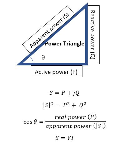
                1) Apparent power
                2) Active power
                3) Reactive power

 1) Apparent power: 

                               The apparent power is denoted as ‘S’. It is the product of the RMS voltage and current. Volt-amperes or VA is unit of the apparent power.
                                S = V x I                 for single phase apparent power
                                S = 1.73 V x I       for three phase apparent power
                                                                                Where V is phase voltage and I is line current


2) Active Power:

                               The active power is also known as true power or real power. This power is a useful power for the load. The unit of the active power is WATT (W) and it is denoted as P. WATT is a very small unit, so power is measured in kW or MW. The active power is carried out in the power system by the part of the current. This current is always in phase with the supply voltage. The real work cannot be done when the current is out of phase with the supply voltage.
3) Reactive power:  
                              The reactive power is a part of an apparent power which is out phase with the real power. This is happening in the power system by reactive elements like inductors and capacitors. This power does not use for the load. The reactive power is also known as the imaginary power. The unit of the reactive power is volt-ampere-reactive (VAR).

Power factor: 

                               The power factor is the ratio of active power (true power) to the power supplied by the power system (apparent power).
                                POWER FACTOR = REAL POWER / APPARENT POWER
                                                                          PF = P/S
In power triangle, θ is the angle between current and voltage. Power factor is also defined as the cosine angle between the phase voltage and the line current.
                                                                             PF = cos θ
Power factor is a dimensionless quantity. The range of power factor is between -1 to 1. In an ideal power system, the power factor is unity (1), means that there is only real power is available. There is absent of reactive power. But in the actual power system, we can not ignore the reactive power and it always is present in the power system. So, in the actual power system, the power system can not unity, but for good quality of supply, we try to maintain power factor near to the unity.
In the power system, we use FACTS devices to improve the power factor.