Showing posts with label Power transmission. Show all posts

Tuesday, 13 November 2018

STATIC VAR COMPENSATOR (SVC)


Static VAR compensator:


The static VAR compensator is also known as SVC. The SVC is a shunt compensator FACTS device. The SVC is a generator or absorber which is used to exchange the capacitive and inductive current from the power system. By this way, it can control and maintain a specific parameter of the system. The SVCs can draw reactive power from the line and improve stability, control over voltage, reduce voltage flickering and regulate voltage. It has capacitor bank fixed or controlled (switched) or fixed capacitor bank and switched reactor bank in parallel. The thyristors are used to control and switching (on & off) of capacitor and inductor. So, it is also known as static VAR switches because it uses switching for VAR control.


For step-wise control of the capacitor and reactor, thyristors in anti-parallel connections are used. In this devices capacitor and reactor unit act as continuously variable in power system, this can be done by controlling of firing angle of thyristors.
There are four schemes for static compensation;
                1) Saturated reactor
                2) Thyristor controlled reactor (TCR)
                3) Thyristor-switched capacitor (TSC)
                4) Combined TCR and TSC compensator
SVC is placed to solve below problems in power system;
* Voltage flickering caused by varying high reactance load like arc furnace
* Transient stability limit
* Power transfer capacity of the transmission line
* Temporary over-voltage in the transmission system
* Regulate the voltage
* To improve power quality
                The SVCs are placed near high and rapidly varying load in industries like arc furnace.

1) Saturated reactor:

                The saturated reactor is a constant voltage reactive source. This is not very flexible with respect to the operating characteristic. This is nothing but a multi-core reactor and the phase winding is arranged to cancel the principal harmonics.

2) Thyristor controlled reactor (TCR):

                It consists of a six-pulse or twelve pulse thyristor-controlled reactors and a fixed shunt capacitor bank. By adjusting the firing angle of the thyristor, the reactive power can control. The control system consists of a voltage and current measuring devices. Filters are used to provide fixed reactive power and absorb the harmonic current generated by TCR. The TCR is used to continuous control of the electrical power system.

3) Thyristor-switched capacitor (TSC):

                It consists of a thyristor-switched capacitor bank. This capacitor bank is split into a number of units to achieve a step-wise control. All the units have an equal rating. By full or zero conduction operation of thyristor valve, the effective resistance of TSC can be varied in a step-wise manner. For effective reactance calculation, we have to consider fully connected or fully disconnected capacitor.

4) Combined TCR and TSC compensator:

                A continuously variable reactive power can be achieved by using a TCR in combination with TSC. A continuous change in the control order from fully lagging to fully leading current is obtained by this combination. By using a different combination, an SVC can get various requirements to absorb/supply reactive power from/to the power system.


Advantages of SVCs:

1) It gives fast response to change in power system
2) Less costly, high capacity, faster and more reliable
3) It reduces harmonics and voltage fluctuations
4) It provides load balancing function
Monday, 12 November 2018

POWER FACTOR

Power factor:

In power system, three quantities are most important;
                1) Voltage
                2) Current
                3) Frequency
Power quality is an important concern in the power system because it affects the voltage, current, and frequency. The power factor is an important aspect for improving power quality of supply. A load with low power factor has good efficiency and it can save a considerable amount of cost. For, this reason, majority of the utility companies demand in the reduction of reactive power. If reactive power demand decrease, the power factor will improve.
 There are three types of power;
                1) Apparent power
                2) Active power
                3) Reactive power

 1) Apparent power: 

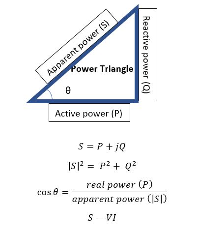
                               The apparent power is denoted as ‘S’. It is the product of the RMS voltage and current. Volt-amperes or VA is unit of the apparent power.
                                S = V x I                 for single phase apparent power
                                S = 1.73 V x I       for three phase apparent power
                                                                                Where V is phase voltage and I is line current


2) Active Power:

                               The active power is also known as true power or real power. This power is a useful power for the load. The unit of the active power is WATT (W) and it is denoted as P. WATT is a very small unit, so power is measured in kW or MW. The active power is carried out in the power system by the part of the current. This current is always in phase with the supply voltage. The real work cannot be done when the current is out of phase with the supply voltage.
3) Reactive power:  
                              The reactive power is a part of an apparent power which is out phase with the real power. This is happening in the power system by reactive elements like inductors and capacitors. This power does not use for the load. The reactive power is also known as the imaginary power. The unit of the reactive power is volt-ampere-reactive (VAR).

Power factor: 

                               The power factor is the ratio of active power (true power) to the power supplied by the power system (apparent power).
                                POWER FACTOR = REAL POWER / APPARENT POWER
                                                                          PF = P/S
In power triangle, θ is the angle between current and voltage. Power factor is also defined as the cosine angle between the phase voltage and the line current.
                                                                             PF = cos θ
Power factor is a dimensionless quantity. The range of power factor is between -1 to 1. In an ideal power system, the power factor is unity (1), means that there is only real power is available. There is absent of reactive power. But in the actual power system, we can not ignore the reactive power and it always is present in the power system. So, in the actual power system, the power system can not unity, but for good quality of supply, we try to maintain power factor near to the unity.
In the power system, we use FACTS devices to improve the power factor. 

Monday, 12 March 2018

Friday, 9 March 2018

Corona effect in power system

Corona effect:

Electric power transmission is practically related to the bulk transfer of power consumption, as well as the construction of stations located at several kilometers away from the main consumption centers or cities. For this reason, long-term transmission cables are highly needed for effective power transfer, which clearly falls into heavy losses across the entire system. To reduce them, there has been a major challenge for late electric engineers and in order to do this, there should be a clear understanding of the nature of nature and nature. In this article, Corona has a major role in the power system to reduce the efficiency of EHV (additional high voltage lines), on which we are going to focus.

What is the effect of Corona in the power system and why does it happen?

In order to effectively reduce the corona effect, two factors are emphasized below, as outlined below: - 

A) Alternatively, the potential potential difference should be given in line. 
B) The spacing of the conductor will be significantly larger than the line diameter.

When an alternate transmission line is done to flow into two conducts, whose distance is larger than their diameter, then the conductor (made of ions) is subject to stress, which depicts the air around it. . There is nothing at the lower prices of the supply end voltage, because the stress is very low to reduce the ion of the air outside. But when the potential difference is known as some important disruptive voltage of about 30 KV, then the strength of the area increases and then the surrounding air experiences high stress, which is different in the anion conducting the atmosphere. Go. Due to the flow of these ions due to the ionized surrounding results in the electrical discharge around the conductor, along with the faint luminescence giving rise to shine, with the sound running with the ozone release. This phenomenon of electrical discharge occurring in the transmission line for high values ​​of voltage is known as the corona effect in the electrical system. If the voltage in the lines still increases, the noise becomes sharper with the noise in the system, the loss of high power in the system is damaged.

Corona Affected Factors in Power Systems:

As previously mentioned, at low prices of voltage, at low rates of voltage, the conductor's line voltage is the main determining factor for corona in transaction lines, stress on the air is very low to separate them, hence no electrical discharges Does not happen. Because of the increasing voltage corona effect in the transmission line due to the ionization of atmospheric air around the cable, it is mainly influenced by the physical condition of the environment along with the conditions of the cable. Now let's look at this criterion, with more details:

Corona's atmospheric conditions in transmission lines:

We have proved that the voltage gradient is directly proportional to the density of air for the dielectric disintegration of the air. Therefore, in a stormy day, due to the continuous air flow, the number of ions present around the conductor is more than the normal, and hence compared to one day compared to one day, electricity in such transmission lines There is a high probability of the flow of clean weather. The system must be designed to consider those extreme situation in transmission Line.

Status of Cables for Corona in Transmission Line:

This special event relies heavily on the conductor and its physical condition. This is an inverse proportional relationship with the diameter of the conductor. That is, with the increase in diameter, the effect of Corona on the power system is greatly reduced; In addition, the presence of dirt or roughness of conductor has reduced significant breakdown voltage, due to which carrier corona is prone to deficit . Therefore, due to high pollution in most of the cities and industrial areas, this factor is of appropriate importance to dealing with the bad effects on the system.

Space between the conductor:

As already mentioned, the corona should be very much effective in the distance between the diameter, but if the length increases more than a certain limit, then the stress decreasing on air decreases, and As a result, the effect of corona as well reduces if the spacing is too large, then the Corona can not be at all for that area of ​​the transmission line.

Skin effect in transmission line

Skin effect:

The incident occurring due to the uneven distribution of the current on the whole cross section of the conductor being used for long distance power transmission is referred to as the skin effect in transmission lines. Such an incident does not have much role playing in the case of a very small line, but the effect of the skin increases significantly with the increase in the effective length of the conductor. Therefore line calculation should be done according to modification.

In the case of DC systems, distribution of current on the entire cross-section of the conductor is quite similar. But what we are currently using in the present era of power system engineering is primarily an alternative system, where at present there is tendency to flow with high density through the surface of conductor (i.e., the conductor's skin), in which Leaving a deprived parent with an essential number of electrons.

In fact, such a situation arises even when there is no current flow through any core, and keeping the entire zodiac in mind on the surface area, thus increasing the effective electrical resistance of the conductor increases. This special tendency of the AC transmission system is referred to as the skin effect in the transmission lines to take the surface path to be deprived of the core for current flow.

After understanding the impact of skin effect, we now see why this happens in case of AC systems. For a clear understanding of this, see the cross-sectional view of the conductor during the flow of alternating turn given in the picture below. Let us consider the concrete conductor at the beginning, in addition to countless short distances to be divided into some uncontrolled fibers, as in each filament there is a small fraction of the total current. Such as total current = I

Let us consider dividing the conductor into the en filament carrying the current 'I', like I = NI Now during the flow of a fine flow, the filaments carrying the current lying on the core have a flux linkage with surface fibers as well as the whole conductor cross-section of the core. While the flux installed by external fibers is limited to the surface and is unable to link to the internal fibers. In this way the flow of the conductor increases the linkage because we move towards the core and the installation increases at the same rate. Its flow is directly related to a direct proportion with the direct result, as a result, compared to the outer sections of the conductor, in a bigger reflexive molecule core Gets motivated At present, the high value of mitigation in the internal segment results is distributed in an equal manner and forces the present to flow through the outer surface or the skin, resulting in the effect of the skin in the transmission lines.

Thursday, 25 January 2018

Transmission line modelling

One of the main difficulties when dealing with transient simulation studies in a digital simulator program is the correct representation of transmission lines.
Lumped and Distributed Transmission Line Model:
            If travelling time of signals in transmission line is small than time step than we can model transmission line in to lumped parameter model. If travelling time is much larger than time than we have to make a distributed parameter model. We cannot take line parameter as lumped parameter.
Lumped Parameter Model:
          PI Model:
                        The nominal PI model are often used for the short transmission line about 15 km, as the travel time of this model is less than time-step, but this model is not appropriate for the long transmission line. All parameters in this model are used in the lumped form. This model is useful for the steady-state analysis, as for single frequency.
Distributed Parameter Model (Travelling Wave Model):
            Three types of model based on distributed parameter model.
1.    Bergeron model
2.    Frequency-Dependent Phase Model
3.    Frequency-Dependent Mode Model
·         Transmission line models which take into account the frequency dependence of the line parameters have become very important tools in the modern analysis of transient phenomena.
·         This model have advantages over constant frequency model. Constant-Frequency models are very easy to use and require relatively little input information.
·         On the other hand, frequency-dependent models require detailed knowledge of the tower configuration and conductor characteristics in order to evaluate the variation of R and L over the frequency range of interest to power transient simulations (i.e. dc to 1 MHz).
·         In the simulation of large power systems, the relative complexity in the manipulation of input data for frequency-dependent models makes their use impractical for all except the most important lines.
·         It is true that constant-parameters models are computationally faster and easier to use, it should be realized that their poor accuracy could adversely affect the outcome of the overall simulation.
·         A compromise between simplicity and accuracy in the modelling of transmission lines is therefore desirable.
Bergeron Model:
·         Bergeron Model is a constant frequency model. In this model, line parameters are taken as a constant frequency. Therefore this model is not accurate for transient analysis of transmission line.
·         Bergeron Model is very easy to implement compared to frequency dependent model. So if a system is very large then it is not possible to implement frequency dependent model in that condition Bergeron model is used. The accuracy of this model is low compared to frequency dependent model.
·         It requires R, L, C and G parameters for each propagation mode (+Ve seq. and zero seq.).


Frequency-Dependent Phase Model:
·         Frequency-dependent phase model is a very accurate model for transient analysis of transmission line.
·         Transmission line parameters are calculated from tower configuration. So, input for this model is tower configuration and conductors’ specification.
·          It is difficult to implement this model if a system is very large. So this model is not applied to secondary transmission line it is useful to model primary transmission for transient analysis.
Frequency-Dependent Mode Model:
·         This model approximates the phase to mode transformation as a constant. It is useful for studies wherever the transient and harmonic behavior of the transmission line is important.
·         It works very well for single conductor lines, 2 horizontal conductors, or for ideally transposed line geometry. It should not be used for untransposed or when multiple towers are modeled on the same right of way.

·         Modal transformation matrix is used to convert phase-domain (ABC) voltage and current to mode domain voltage and current (αβο).